Thermocouple compensation cables are engineering marvel transmission lines that carry vital micro-voltage (mV) level signals, obtained from temperature sensors at the heart of furnaces, reactors, and heavy industrial machinery in industrial facilities, to the control devices in the automation panel without experiencing any loss or interference. In today's modern factories boasting Industry 4.0 standards, the absolute accuracy of the data collected from the field is the most fundamental element determining production quality. Even if you install hundreds of thousands of dollars worth of state-of-the-art PLC (Programmable Logic Controller) systems or highly precise PID temperature controllers, if you make the wrong choice in the cable infrastructure—the signal highway between the sensor and the panel—your entire investment will go to waste.
The number one suspect behind the frequently encountered erroneous temperature readings, unnecessary overheating or cooling of furnaces, fluctuations in product quality, and unexplained system downtimes in the industry is generally an incorrect or poor-quality extension cable. In this detailed B2B guide, prepared with the expertise of the industry's reliable engineering partner, ThermoKoTec, we will put the physics of data transmission in thermocouple systems, the critical metallurgical differences between extension and compensation cables, insulation materials suitable for your process's atmosphere, and fatal electrical mistakes made during the installation phase on the table with all their engineering details.
Due to their structure, thermocouples do not operate by changing resistance (Ohms) like PT100 resistance thermometers, but entirely by a thermodynamic principle known as the Seebeck Effect. When the ends of two different metal alloys are joined and heated, an electromotive force (EMF), or millivolts (mV), is generated between the heated point and the cold point due to electron mobility. For the temperature at the tip of the sensor to be calculated correctly, the reference temperature at the panel where the measuring device is located (the cold point) must be known very clearly, and the micro-voltage coming from the sensor must reach the panel without undergoing any changes along the way.
The most frequent fatal engineering mistake made by technical teams installing machines or performing revisions in the industry is purchasing a high-quality Cabled Thermocouple and then attaching a standard electrician's copper cable (for example, a TTR cable) to the end of this sensor to cover the distance to the panel. If you connect a standard copper cable to the metal alloy of the thermocouple, you create a new and unwanted "parasitic junction" at the terminal block where these two different metals meet, just like the one at the tip of the sensor. Depending on the ambient temperature, this new connection point will either generate an extra millivolt on its own or dampen the existing millivolt. As a result, the value you see on the control device's screen will not be the actual temperature of the furnace, but rather the random numbers of an electrical chaos. To carry the pure millivolt value generated by the sensor to the panel, special alloy cables that carry the exact same thermoelectric properties as the metals inside the sensor must absolutely be used.
Although they are all colloquially referred to as "thermocouple cables" in the market, under international standards (IEC, ANSI), these transmission lines are divided into two main categories according to their metallurgical structures. The cost optimization and precision expectations of your process directly influence this choice.
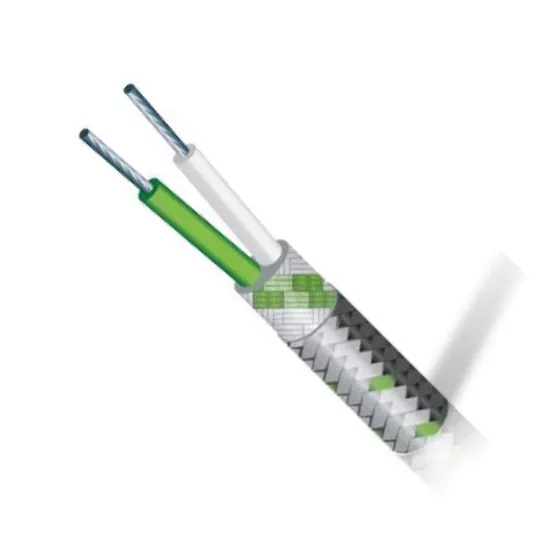
Extension cables are manufactured from the exact same metals present in the positive and negative legs of the measuring thermocouple. That is, if you have a Type K (NiCr-Ni) thermocouple, the wires inside the extension cable also consist purely of Nickel-Chromium and Nickel-Aluminum alloys. In international coding, they are identified by adding the letter "X" next to the sensor letter (For example; KX, JX, TX, EX).
Advantages: Because they are the exact same alloy as the sensor, they are not affected by ambient temperature fluctuations and carry the signal with 100% accuracy and zero error.
Areas of Use: The aerospace industry, pharmaceutical reactors, calibration laboratories, and highly sensitive processes where the temperature reference must be absolute.
Disadvantages: They are quite expensive due to their alloys. Their costs are particularly high if hundreds of meters of lines are to be laid across a large factory floor.
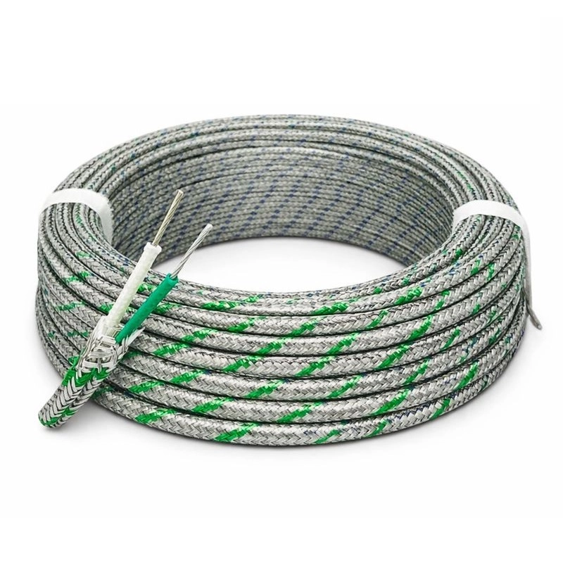
For example, when a KCB type compensation cable is used for a Type K sensor, the positive leg of the cable is made of Copper, and the negative leg is made of a Copper-Nickel alloy. Because pure NiCr-Ni is not used, the cost drops dramatically.
Advantages: They provide immense cost savings in large-scale installation projects. Especially the high-quality compensation models in the Cables category more than meet general industry standards.
Areas of Use: Ceramic kilns, plastic injection machines, iron and steel plants, and the general lines of industrial automation.
Things to Consider: If the environment where the compensation cable is laid (the cable tray or inside the panel) exceeds 200°C, the mimicking feature deteriorates, and the cable begins to transmit incorrect millivolts.
No matter how high the quality of the inner wire alloy is, if the outer plastic sheath (insulation) protecting that wire cannot withstand the harsh physical conditions of your factory, the cable will short circuit. The chemistry of the environment where the cable will operate, the humidity rate, the radiant heat it will be exposed to, and the possibility of mechanical friction determine the outer sheath material.
This is the most common and economical solution. They generally operate in ambient temperatures between -20°C and +105°C. They provide excellent insulation against water and moisture. They are safely used inside the factory, in cable trays in attics, and in under-panel connections that are not excessively hot. However, they lack resistance to acidic environments and direct flames.
If the cable passes near motor blocks, is close to the doors of drying ovens, or needs to retain its flexibility, silicone outer sheaths are preferred. It operates between -40°C and +200°C without losing its form. It does not freeze and break in extreme cold, nor does it become gummy in the heat. However, it is weaker than PVC against mechanical friction (cutting surfaces).
It is the indispensable choice for demanding processes where chemical resistance and high temperatures are required simultaneously. It operates between -200°C and +260°C. It is the standard in paint shops, chemical acid reactors, petrochemical plants, and the aerospace sector. It is non-flammable, non-stick, and remains completely unaffected by corrosive vapors.
Right above furnaces, in iron-steel foundries, or around crucibles, the ambient temperature can easily reach 400°C. In these spots, all plastic-derivative sheaths melt. In such areas of extreme radiant heat, heavy-duty cables with inner and outer insulation woven from fiberglass threads and covered with a stainless steel braid (armor) are used. The steel braid both reflects the heat and protects the cable against machine impacts.




 EN
 Türkçe