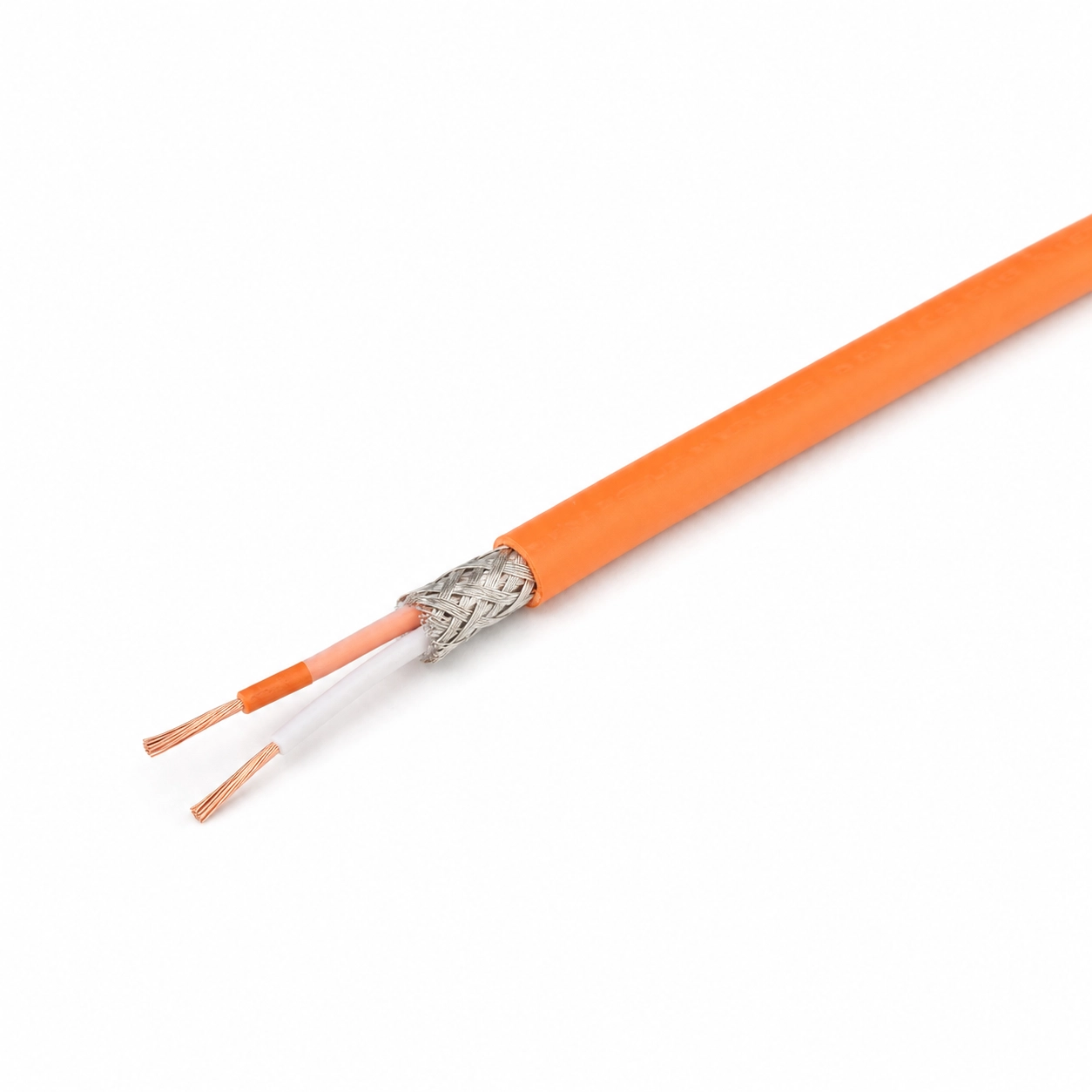
R/S-Type Cu/CuNi Metal-Braid Shielded Teflon Compensating Cable 2x0.22 mm² is a shielded temperature measurement cable used for suitable compensating connections of R-Type and S-Type thermocouple sensors. It extends the measurement circuit between the thermocouple sensor and the temperature indicator, controller, data logger, PLC, or automation system.
The cable consists of two stranded measurement cores, PTFE / Teflon core insulation, a metal braided shield, and an orange PTFE / Teflon outer sheath. Each measurement core consists of 7 wires, each 0.20 mm in diameter, and has a nominal conductor cross-sectional area of approximately 0.22 mm².
The positive conductor consists of copper and the negative conductor consists of CuNi-based compensation alloy. Orange positive (+) and white negative (-) cores are used in the product in accordance with the IEC type color scheme.
The metal braided shield helps reduce the effect of motors, inverters, contactors, relays, power cables, and similar electrical noise sources on the low-level thermocouple measurement signal. This model has no separate drain wire. When a shield connection is required, the metal braid must be terminated using an appropriate method.
This product is not an actual platinum-rhodium thermocouple element or sensor-manufacturing wire. It is a compensating cable with Cu/CuNi conductors designed for use in the compensating circuit of R/S-Type thermocouple systems.
The measuring tips of R and S-Type thermocouple sensors consist of precious metal-based thermoelements. Instead of the same precious metal alloys as the sensor element, copper and copper-nickel based conductors are used in the compensating cable, which provide appropriate thermoelectric behavior under certain connection conditions.
In this product, the conductor of the orange positive core is copper. It is normal for the conductor to appear copper-coloured when the cable end is stripped. The CuNi-based conductor used in the white negative core has a gray or silver appearance.
The stranded-conductor construction makes the cable easier to shape for control-panel, instrument, and terminal connections. Each core is formed from 7 wires, each 0.20 mm in diameter.
Metal braided shieldis the conductive layer around the positive and negative measurement cores. It helps to reduce the electromagnetic and electrostatic effects from the external environment reaching the measurement line.
Drain wire is a separate conductor that is in electrical contact with the metal braid in some shielded cables and facilitates connecting the shield to a terminal.
Although this model has a metal braided shield, it does not have a separate drain wire. When shield connection is required, the metal braided shield must be carefully assembled and terminated at the appropriate shield, chassis or ground terminal.
| Cable Component | Primary Function | Connection |
|---|---|---|
| Orange measurement core | Positive conductor of the R/S-Type compensating circuit. | It is connected to the positive (+) terminal of the device. |
| White measurement core | Negative conductor of the R/S-Type compensating circuit. | It is connected to the negative (-) terminal of the device. |
| Metal braided shield | It helps reduce the effect of electrical interference on the measurement line. | When necessary, it is terminated at the appropriate shield, chassis or ground terminal. |
| Teflon outer sheath | It isolates the inner cores and the metal braided shield from environmental effects. | It is not an electrical connection component. |
This R/S-Type compensating cable uses the IEC-type orange-and-white color scheme to distinguish the cores and their polarity.
Different color coding systems such as IEC, ANSI and JIS can be used in thermocouple cables. The same thermocouple type may have different core and outer sheath colors depending on the standard used.
When making a connection, no action should be taken based solely on the cable color. Thermocouple type, conductor structure of the compensating cable, positive-negative polarity markings and device terminal diagram should be checked together.
The compensating cable ensures that the connection line between the thermocouple sensor and the measuring instrument is maintained with the appropriate electrical characteristic. It is used to transmit the low-level measurement signal from the sensor to the controller.
This product's conductors consist of copper and a CuNi-based alloy. They do not have the same construction as the precious-metal thermoelements at the hot measuring junction of an R- or S-Type thermocouple.
For this reason, the orange and white cores must not be joined to form an R- or S-Type thermocouple measuring junction. The product must be used only in a suitable compensating connection circuit.
Thermocouple sensors produce a low-level voltage signal. This signal may be affected by electrical noise from motors, inverters, contactors, relays, heating-element control systems, and power cables.
The metal braided shield creates a conductive layer around the positive and negative measurement cores, helping to reduce external electrical influences from reaching the measurement line.
This structure can be preferred especially in thermocouple connections passing near control panels, industrial machines, drive systems and power cables.
The metal braided shield does not completely eliminate electrical interference. Its effectiveness depends on the cable route, shield connection, grounding arrangement, device input configuration, and level of electrical noise in the environment.
In the R/S-Type thermocouple compensation circuit, the orange wire should be connected to the positive (+) terminal of the device and the white wire should be connected to the negative (-) terminal.
Reverse polarity may cause the measurement value to change in the wrong direction or the indicator to decrease as the temperature rises. The terminal markings of the device should be checked before connection.
The metal braided shield should not be connected to the positive or negative measurement terminal. If shield connection is required, the braid should be carefully assembled and terminated at the appropriate shield, chassis or ground terminal.
Because this model has no separate drain wire, a suitable connection end may need to be prepared from the braid so that it can be connected to a terminal. The braid wires must not contact the measurement cores.
It is preferred for the shield to be terminated from a single point on the controller or board side in most measurement applications. The exact connection method must be determined according to the device manufacturer's terminal diagram and the EMC/grounding project of the facility.
The cable should not be run parallel to power cables for long distances in the same channel. Separating power and measurement cables as much as possible supports measurement stability and shielding performance.
No. The main function of the metal braid in this product is electrical shielding. Although braid can provide some physical support to the cable, it should not be considered heavy-duty mechanical armor.
On routes where there is a risk of crushing, cutting, intense friction or mechanical impact, the cable must also be carried in a protective spiral, pipe or appropriate cable duct.
When choosing a cable, thermocouple type, compensation class, conductor alloy, core cross-section, color code, insulation material, shielding requirement, cable route and the device to be connected should be evaluated together.
This product is for suitable compensation lines of R and S-Type thermocouples. It should not be used in measurement circuits of K, J, T, E, N or different thermocouple types.
If the cable is planned to be used in a hot area close to the sensor, ambient temperature and connection conditions should be checked according to the manufacturer's technical documentation. Teflon general properties of the material alone should not be considered the exact operating temperature of the product.
The product is designed for use in appropriate compensation connections of R and S-Type thermocouple systems.
No. The product is a compensating cable with Cu/CuNi conductors. It is not the precious metal thermoelement wire used in the actual R or S-Type thermocouple element.
No. R or S-Type thermocouple sensors should not be produced by combining orange and white cores. The cable should only be used for compensation connection purposes.
According to the IEC type color scheme, the orange wire indicates positive (+) and the white wire indicates negative (-) compensation connection. The outer sheath is also orange.
Yes. The conductor of the positive core is copper. When the cable is stripped, the conductor appears in copper color, which is compatible with the technical structure of the product.
CuNi-based compensation alloy is used in the white negative core. This conductor may appear gray or silver, rather than red like copper.
No. The metal braid is the shield layer surrounding the measurement cores. The drain wire is a separate conductor that facilitates the connection of the shield to the terminal. This product does not have a separate drain wire.
Yes. The metal braid can be collected appropriately and terminated at the shield, chassis or ground terminal. The connection must be made in accordance with the device diagram and the braid must not come into contact with the measurement cores.
It indicates that the cable has two measurement cores, each with a nominal conductor cross-sectional area of approximately 0.22 mm².
It means that each measurement core is made of 7 thin wires with a diameter of 0.20 mm. The stranded structure helps the cable to be shaped more easily.
No. The metal braided shield helps reduce the effect of electrical noise on the measurement line. The result depends on the cable route, shield connection, grounding pattern and the level of interference in the environment.
No. The product is used to transmit a low-level thermocouple measurement signal. It must not be used to power a motor, heating element, heater, or any other electrical load.
The manufacturer's technical data sheet should be used as the basis for the product's exact operating temperature, shield alloy, electrical values, outer diameter tolerance and continuous use conditions. Values not verified by the manufacturer should not be considered the exact application limit of the product.




 EN
EN Türkçe