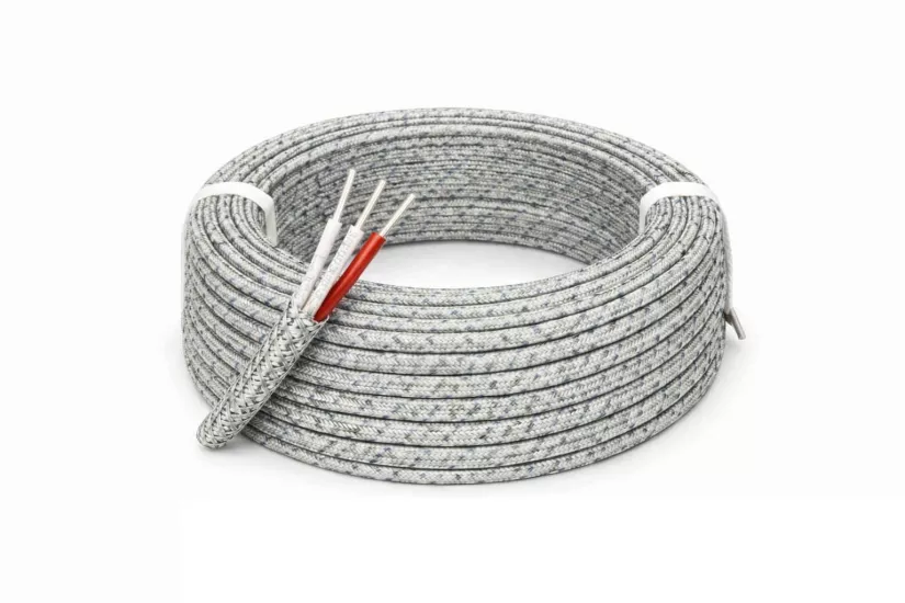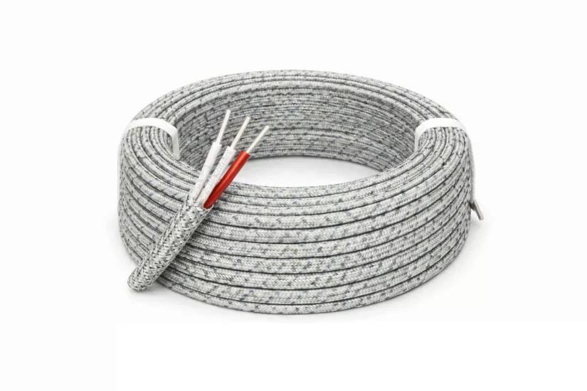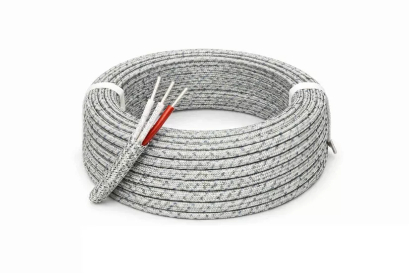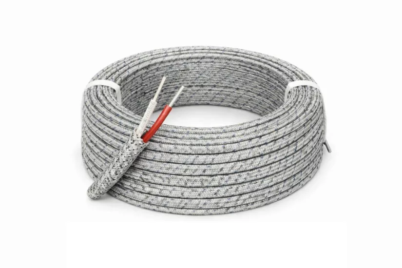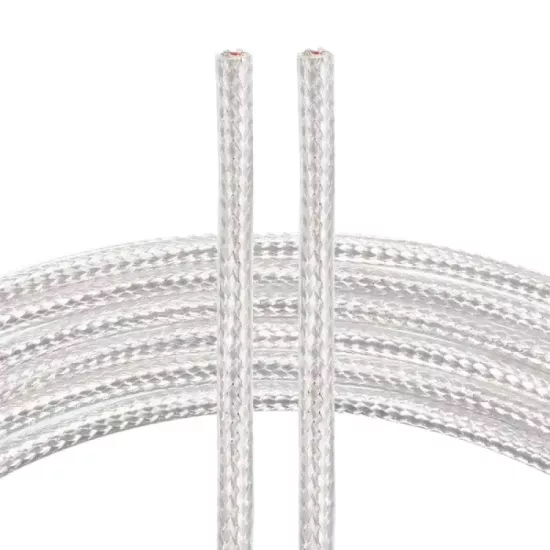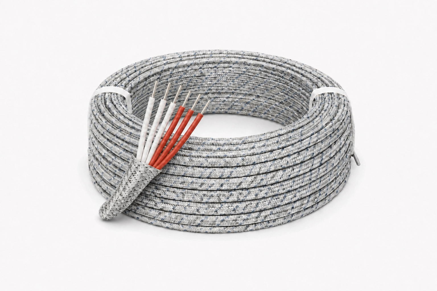
PT100 Cable 6x0.22 mm² is a six-core sensor cable prepared for RTD/PT100 sensor connections in industrial environments with high temperature effects. It can be used in measurement connections between the PT100 sensor and the temperature indicator, controller, data logger, PLC RTD input or control panel.
With its six-core construction, fiberglass inner insulation, fiberglass outer braid, and steel braid, the cable is suitable for fixed sensor connections exposed to heat. The fiberglass layers help maintain electrical insulation in high-temperature connections, while the steel braid provides supplementary mechanical protection for the cable body.
A primary application of the six-core construction is the connection of dual-element PT100 sensors. When each PT100 measuring element is used with a three-wire connection, three wires are required for the first sensor element and three wires for the second sensor element. Thus, two independent three-wire PT100 measurement circuits can be carried over the same cable.
This product is not a thermocouple cable or a power supply cable. It should be used to transmit the temperature-dependent resistance change of PT100 and compatible RTD sensors to measuring instruments. The sensor's single- or dual-element construction, wiring diagram, and the instrument's RTD input characteristics should be checked before installation.
Fiberglass insulation used in the cores and outer parts of the cable is preferred in high-temperature fixed sensor connections where standard plastic insulations are not suitable. It can be evaluated in PT100 connections around the furnace, heat treatment equipment, hot mold, machine body and process line.
Fiberglass structure helps to electrically separate the cores and maintain cable integrity in applications where high temperatures directly or indirectly affect the cable route.
The exact operating temperature of the product should not be determined solely by looking at the fiberglass insulation. The temperature limits of the conductor construction, outer braid, steel braid, terminal, connector, sensor output and splice points should be evaluated together.
The cable should not be placed in direct contact with flame and should not be used at temperatures not verified by the manufacturer. For continuous and instantaneous operating temperature, the manufacturer's technical data must be used as the basis.
The designation 6x0.22 mm² indicates that the cable consists of six individual cores and that each core has a nominal conductor cross-section of 0.22 mm². The six-core construction is specifically used for the combined carriage of two independent three-wire PT100 connections.
A standard three-wire PT100 measuring element uses three cores. When the dual-element PT100 sensor contains two independent measuring elements, a separate three-wire connection is made for each element. Thus, a total of six cores are required.
The six-core structure can also be used to carry the connections of two separate three-wire PT100 sensors on the same route within a single cable body, if the connection project is suitable.
The presence of six cores does not mean that all cores will be used in every application. In single element PT100 sensors, unused cores should not be connected to each other and their open ends should be properly isolated.
The dual element PT100 sensor is a sensor structure with two separate and electrically independent PT100 measuring elements within the same sensor body. Two elements can monitor the temperature at the same measuring point but are connected to separate measuring channels.
In the dual-element sensor, the first three-wire group is connected to the first PT100 element, and the second three-wire group is connected to the second PT100 element. Each group must be clearly identified at both ends of the cable and the same core arrangement must be maintained.
Two PT100 elements must be connected to two independent three-wire RTD inputs on the measurement side. A controller with a single RTD input cannot independently measure two sensor elements simultaneously.
The dual element PT100 sensor structure can be preferred in the following applications:
Two PT100 measuring elements must not use common cores unless expressly stated in the sensor manufacturer's wiring diagram. Each sensor element must be considered an independent three-wire measurement circuit.
PT100 is a RTD sensor whose electrical resistance changes depending on temperature. Unlike thermocouples, it does not produce thermoelectric voltage and there is no positive-negative polarity in the PT100 measuring element.
In the three-wire connection, two wires are connected to one side of the PT100 measuring element and one wire is connected to the other side. The length, nominal cross-section, conductor structure and connection points of two cores connected to the same side should be as similar as possible.
When the measuring instrument supports three-wire RTD input and the electrical characteristics of the relevant cores match each other, it can help compensate for the effect of connecting wire resistance on the measurement.
When using a dual element sensor, this connection scheme is applied twice. The first three-wire group is connected to the first RTD input, and the second three-wire group is connected to the second RTD input.
The product consists of three red and three white cores. For each three-wire PT100 connection, the conductors must be grouped according to the sensor manufacturer's diagram.
Since PT100 is a resistance-based sensor, the red and white cores do not indicate positive-negative polarity. Core colors make it easy to distinguish between leads connected to the same sensor side and different measurement groups.
In a double sensor connection, the core groups of the first and second PT100 element must be labeled at both ends of the cable. It is not appropriate to group cores randomly based only on their color.
The sensor wiring diagram and the measuring instrument RTD terminal descriptions must be verified before installation. Core colors alone do not prove official standard compliance or certification.
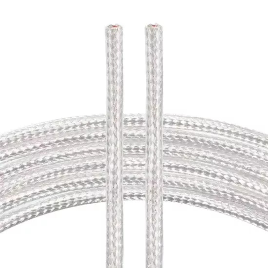
The six cores are separated from one another by fiberglass-based insulation. In addition to the core insulation, the outer fiberglass braid holds the cable bundle together and supports the outer construction in connections exposed to high temperatures.
The fiberglass braided surface is different from standard PVC or similar plastic outer sheaths. During assembly, the cable should not be crushed, rubbed against sharp edges, or pulled in a way that will disperse the fiberglass braid.
If there is a possibility of direct contact with a hot surface in the cable route, the surface temperature, contact time and verified operating limits of the cable should be evaluated together.
The steel braid around the cable provides auxiliary mechanical protection to the fiberglass cable trunk. It helps protect against friction and light mechanical effects on routes where there is a risk of contact, such as the machine body, panel passage, metal surface and cable duct.
The steel braid supports the outer construction of the cable in high-temperature industrial environments. However, it does not protect the cable indefinitely against heavy impact, crushing, cutting or excessive pulling force.
The main function of steel braid is mechanical protection. To be considered an electrical shield, the material of the braid, its electrical continuity, coverage structure and connection method must be verified with the manufacturer's technical data.
The grounding or shield connection of the shield should not be made the same way in every application. The connection instructions of the measuring instrument manufacturer, the electrical project and the grounding structure of the facility should be used as the basis.
Fiberglass insulation is a preferred structure in industrial sensor connections where high temperature effects are present. However, the exact continuous and instantaneous temperature limits of the cable must be determined according to the manufacturer's technical documentation.
The steel braid does not transform the cable into a completely enclosed or leak-proof outer sheath. In environments where there is moisture, liquid, oil, chemicals or dense dust, the product's compliance with environmental conditions should also be checked.
The cable should not be subjected to excessive pulling force, crushing, sharp edges or repeated bending. The product should first be evaluated for fixed sensor connections.
When planning the cable route in high temperature applications, the possibility of hot surfaces, radiant heat, moving parts, vibration and mechanical contact should be evaluated together.
Points such as the sensor output, cable splice, terminal box and device connection may have a lower temperature limit than the cable itself. The operating temperature of the system is determined by the component with the lowest resistance value.
In the double-element PT100 sensor connection, the six wires must be arranged in two separate three-wire groups. The first core group should be connected to the first PT100 element, and the second core group should be connected to the second PT100 element.
Core groups should be clearly labeled at both ends of the cable and the same group arrangement should be maintained. Mixing the cores of two sensor elements may result in inaccurate or unstable measurements.
Each PT100 element must be connected to a separate three-wire RTD input on the measuring instrument. If the measuring instrument only has a single RTD input, two PT100 elements cannot be measured independently at the same time.
In the three-wire RTD connection, the length, nominal cross-section and conductor properties of the cores used in the same measuring branch must be compatible.
If it is necessary to make additions to the cable, the same conductor structure, nominal cross-section and connection method should be used in each three-core group. Loose, oxidized or divergent connections may affect the measurement result.
While preparing the cable end, care should be taken not to disperse the fiberglass braid more than necessary. The outer braid must be opened in a controlled manner without damaging the core insulation.
Steel braid wires must not come into contact with the measurement cores or device terminals. The shield must be properly removed and exposed metal wires must be properly contained.
The PT100 cable should be routed as far as possible from motor supply lines, inverter outputs, contactor lines and high-current power cables.
When selecting the PT100 cable, the single or double element structure of the sensor, the connection type of each element, the number of RTD inputs on the measuring instrument, the number of cores, connection distance, operating temperature, insulation and mechanical protection needs should be evaluated together.
Single-element PT100 sensors often use two-, three- or four-wire connections. In PT100 sensors, which have double elements and three wires in each element, a total of six cores are used because two separate three-wire connections are required.
This product, with its 6x0.22 mm² structure, should be considered especially for double element PT100 sensor connections where high temperature effects are present.
Fiberglass insulation provides advantages in fixed connections with high temperature effects, and steel braid provides advantages in routes where superficial mechanical protection is required. The exact selection should be made by comparing the technical documentation of the sensor, cable and measuring instrument.
The six cores are specifically used for the connection of double element PT100 sensors. When each PT100 measuring element is connected with three wires, a total of six wires are required for two independent sensor elements.
Due to its fiberglass inner and outer insulation structure, it can be preferred in fixed PT100 sensor connections where high temperature effects are present. The exact operating temperature must be determined according to the manufacturer's technical documentation.
A dual element PT100 sensor is a sensor with two separate and electrically independent PT100 measuring elements within the same sensor body. Each element can be connected to a separate measurement channel.
The first three wires are connected to the first PT100 measuring element, the other three wires are connected to the second PT100 measuring element. Each sensor element must be connected to a separate three-wire RTD input on the measuring instrument.
If the measuring instrument has two independent three-wire RTD inputs, two PT100 elements can be connected to the same device via separate channels. Two elements cannot be measured independently at the same time on a device with a single RTD input.
Dual sensor structure can be used to separate main and backup measurement, control and safety channels, to compare two measurement values or to monitor the same measurement point by two different systems.
This statement indicates that the cable consists of six separate cores and each core has a nominal conductor cross-section of 0.22 mm².
No. PT100 is a resistor-based RTD sensor and does not have positive-negative polarity. Core colors make it easier to distinguish connection groups.
Fiberglass insulation helps protect the electrical insulation and cable structure in high-temperature sensor connections where standard plastic insulations are not suitable.
Exact operating temperature depends on the technical values of the conductor, fiberglass insulation, steel braid, terminal and connection elements. The exact temperature range should not be specified without verified manufacturer data.
The steel braid creates auxiliary mechanical protection around the cable trunk. It helps protect the cable against friction and surface mechanical effects.
In order to be considered an electrical shield, the electrical continuity of the braid, coverage structure, connection method and manufacturer's technical data must be checked. The main function of the steel braid is mechanical protection.
No. This product should be used in measurement connections of PT100 and compatible RTD sensors. It should not be used to power motors, heating elements or other electrical loads.
The manufacturer's technical data sheet should be used as the basis for the conductor material of the cable, actual core resistance, continuous and instantaneous operating temperature, outer diameter, steel braid material, minimum bending radius and environmental resistance limits.
During product selection and installation, the single or double element structure of the PT100 sensor, the connection type of each element, the number of inputs of the measuring instrument RTD, cable length, terminal structure, ambient and surface temperature, radiant heat, mechanical loads and cabling route should be evaluated together.




 EN
EN Türkçe