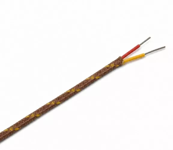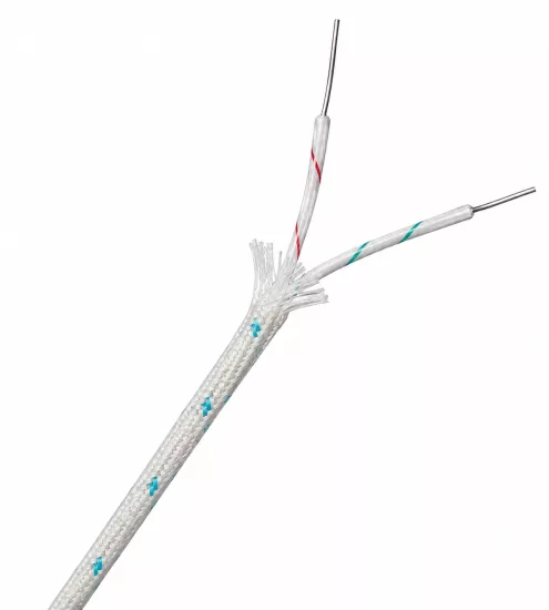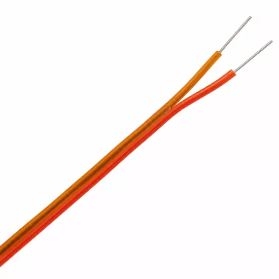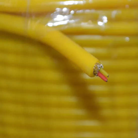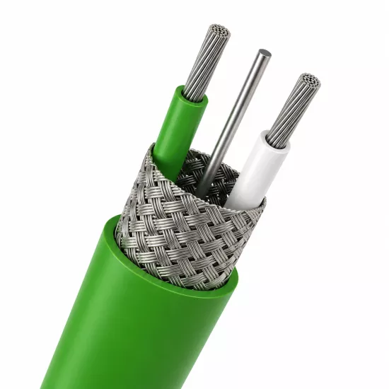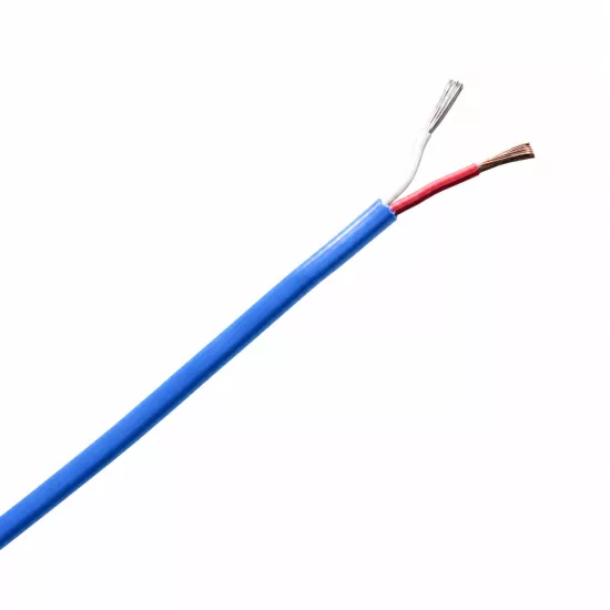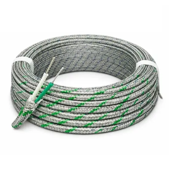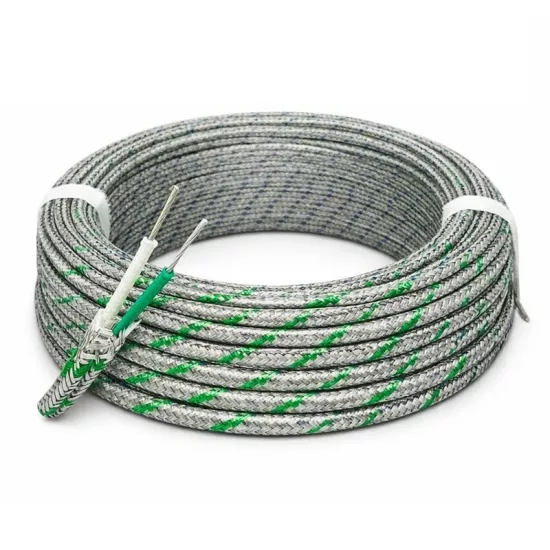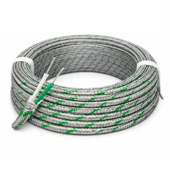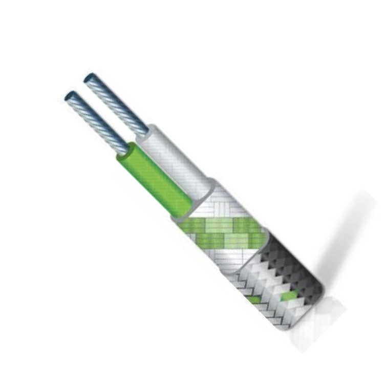
K-Type NiCr-Ni Thermocouple Cable 2x0.22 mm² is designed for use in the thermoelectric signal connection between the K-Type thermocouple sensor and the temperature measuring instrument. It can be used in sensor, controller, indicator, data logger, PLC thermocouple input and control panel connections.
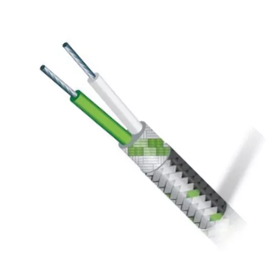
The two-core cable structure has fiberglass insulation layers and a steel braid on the outside. While fiberglass insulation is preferred in industrial connections where temperature effects are present, the steel braid helps protect the cable body against friction and surface mechanical effects.
This product is not a power supply cable. It should be used in K-Type thermocouple measurement circuits. For accurate measurement, the sensor type, cable type and device input must be compatible with the K-Type thermocouple connection. Positive and negative polarity must be maintained throughout the connection.
The two cores of the cable are separated from each other by a fiberglass-based insulation structure. Additional fiberglass braid in the outer layer helps hold the cores together and protect the cable body.
The steel braid around the cable provides additional mechanical protection to the outer surface for fixed sensor connections. It helps protect the cable against friction and light mechanical effects on routes with machine body, panel passage or surface contact.
The main function of the steel braid is mechanical protection. If the shield is planned to be used as an electrical shield, the electrical continuity of the braid, coverage structure, connection type and device manufacturer's instructions should also be evaluated.
Using a thermocouple cable compatible with the sensor type helps reduce measurement deviations that may result from improper metal connections in the measurement line.
2x0.22 mm² section structure. It can be used in thermocouple measurement circuits with suitable terminal area, cable route and connection distance. When selecting the cross-section and cable length, the connection structure of the system, mechanical conditions and device terminal dimensions should be evaluated together.
Fiberglass insulation is a preferred structure in industrial sensor connections where temperature effects are present. However, the exact operating temperature of the product should not be determined solely by the insulation material.
Conductor structure, fiberglass insulation, outer braid, connection terminals, connectors and mounting points must all comply with the operating conditions of the system. For exact temperature limits, the manufacturer's technical data must be used as the basis.
The steel braid does not turn the cable into a completely closed and leak-proof outer sheath. In environments where there is moisture, liquid, oil, chemicals or dense dust, the product's compliance with environmental conditions should also be checked.
The cable should not be subjected to excessive pulling force, crushing, sharp edges or repeated bending. The steel braid helps with mechanical protection, but does not indefinitely protect the cable from heavy mechanical loads.
In the K-Type thermocouple connection, the positive and negative conductors must be connected to the corresponding terminals on the sensor and measuring instrument. Since core colors may vary depending on the manufacturer or the applied color standard, the connection should not be made based on color alone.
Before installation, sensor polarity, cable ends and device terminal markings must be checked. Reverse polarity may cause the temperature change to appear in the wrong direction on the device or cause incorrect measurement values.
Cable, terminal and thermocouple connector compatible with K-Type must be used in the K-Type thermocouple circuit. Cables of different thermocouple types or unsuitable connectors may create additional metal connections in the measurement line, affecting the measurement result.
While preparing the cable end, care should be taken to ensure that the steel braid wires do not come into contact with the thermoelement conductors or device terminals. The shield must be properly removed and the connection area must be isolated in accordance with the application.
Thermocouple cable should be routed as far as possible from motor supply lines, inverter outputs, contactor lines and high-current power cables.
The product is available in cable lengths of 1, 2, 3, 4, and 5 meters. When ordering, the appropriate length is selected using the Cable Length must be selected from the field.
There is a separate product code and variant barcode for each cable length. Variant information is shown in the table below.
| Product Code | Sensor Type | Conductor Structure | Insulation | Cable Length | Product Barcode |
|---|---|---|---|---|---|
| K-CCB-2-0,22-Ç-1K | K-Type (NiCr-Ni) | 2x0.22 mm² | Fiberglass + fiberglass + steel braid | 1 Meter | 759618174398 |
| K-CCB-2-0,22-Ç-2K | K-Type (NiCr-Ni) | 2x0.22 mm² | Fiberglass + fiberglass + steel braid | 2 Meters | 791042499234 |
| K-CCB-2-0,22-Ç-3K | K-Type (NiCr-Ni) | 2x0.22 mm² | Fiberglass + fiberglass + steel braid | 3 Meters | 791042499241 |
| K-CCB-2-0,22-Ç-4K | K-Type (NiCr-Ni) | 2x0.22 mm² | Fiberglass + fiberglass + steel braid | 4 Meters | 791042499258 |
| K-CCB-2-0,22-Ç-5K | K-Type (NiCr-Ni) | 2x0.22 mm² | Fiberglass + fiberglass + steel braid | 5 Meters | 791042499265 |
When determining the cable length, the actual route between the sensor and the measuring instrument, the connection distance within the panel, the turning points and the mounting allowance required for the terminal connection must be taken into account.
An excessively short cable may create tensile stress at the connection points. If the cable is longer than necessary, it may cause unnecessary cable accumulation in the panel or machine. The length closest to the installation route should be selected.
This product should be used for K-Type NiCr-Ni thermocouple sensors and measurement circuits.
The expression NiCr-Ni indicates the thermoelement pair used in the K-Type thermocouple circuit. K-Type thermocouple compatibility and correct polarity must be maintained throughout the connection.
This statement indicates that the cable consists of two cores and each core has a nominal conductor cross-section of 0.22 mm².
Fiberglass insulation is preferred in industrial sensor connections where temperature effects are present. Exact temperature limits must be evaluated according to the manufacturer's technical documentation.
The steel braid creates an additional layer of mechanical protection around the cable trunk. It helps protect the cable against friction and surface mechanical effects.
The main function of the steel braid is mechanical protection. In order to be considered an electrical shield, the electrical continuity of the braid, coverage structure, connection method and manufacturer's technical data must be checked.
This product should be selected for K-Type thermocouple measurement circuit. For J, T, N, E, R, S or different thermocouple types, a thermocouple cable compatible with the relevant sensor type must be used.
No. This cable is prepared for transmitting the thermocouple measurement signal. It must not be used to power heating elements, motors, or other electrical loads.
From the cable length field on the product page, the length appropriate to the installation route should be selected from 1, 2, 3, 4 or 5 meter options.
The manufacturer's technical data sheet should be used as the basis for the exact operating temperature of the cable, conductor construction, thermoelement tolerance, core colors, outer dimension, steel braid material, minimum bending radius and environmental resistance limits.
During product selection and installation, sensor type, device input, cable length, terminal structure, ambient temperature, humidity, mechanical loads and cabling route should be evaluated together.




 EN
 Türkçe