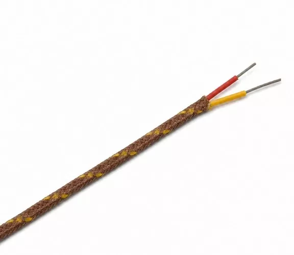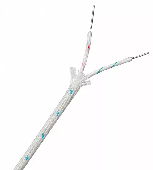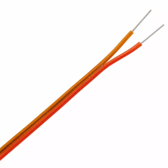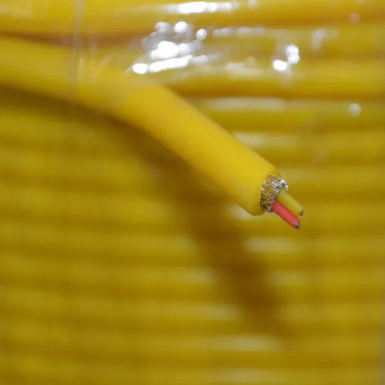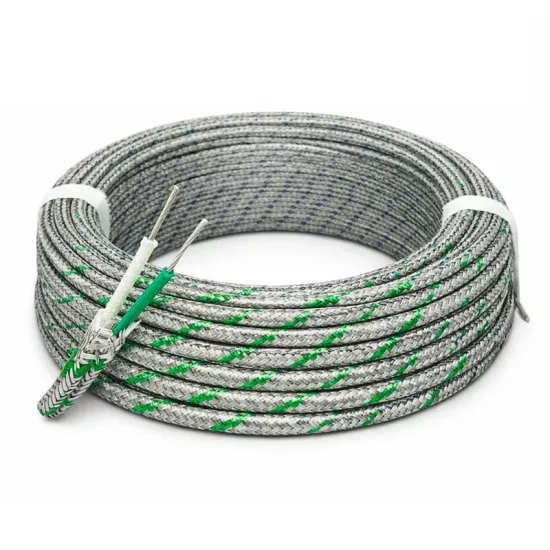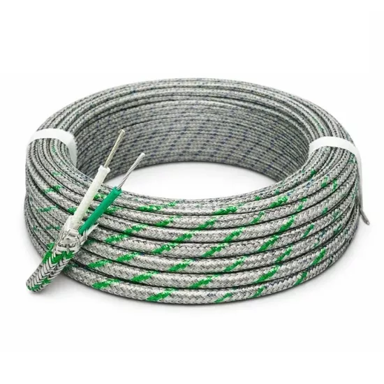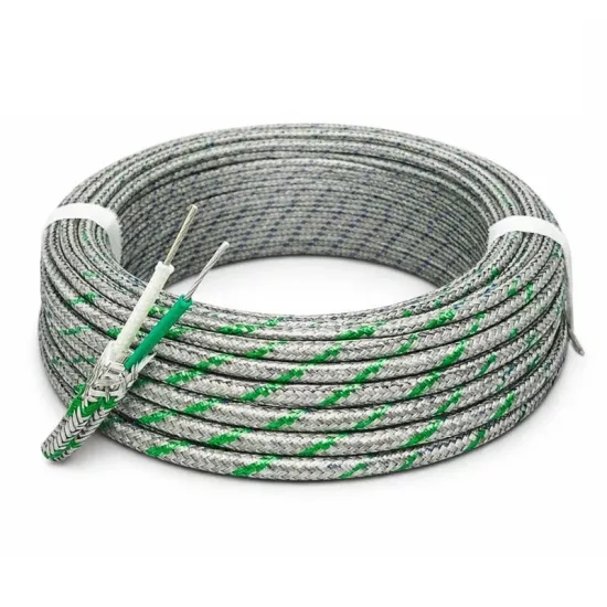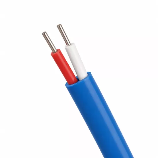
K-Type Shielded Thermocouple Cable 2x0.22 mm² + 0.50 mm² Drain Wire is a shielded thermocouple connection cable used to transmit the low-level temperature measurement signal received from the K-Type thermocouple sensor to the controller, indicator, data logger, PLC or automation system.
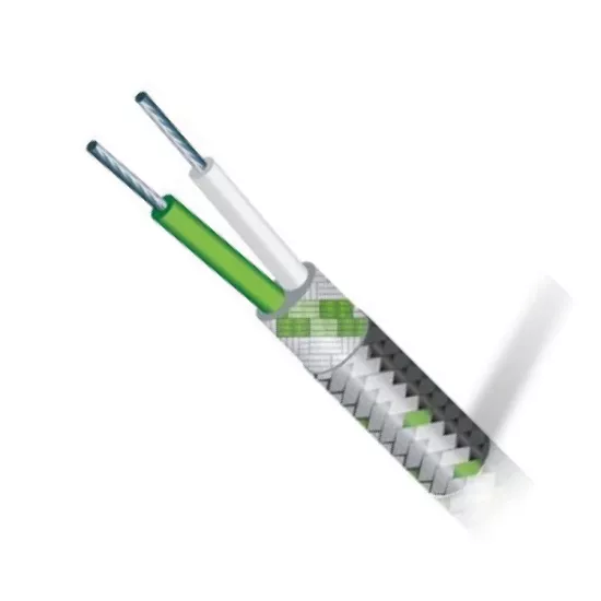
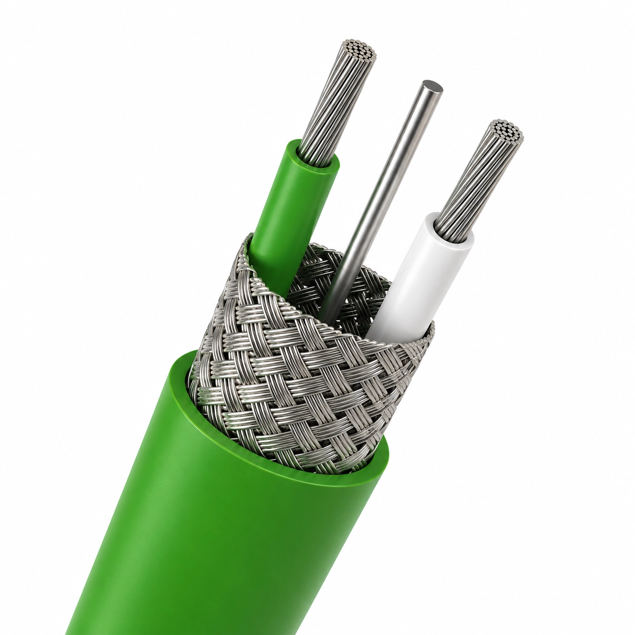
The cable consists of two K-Type measurement cores, a metal braided shield surrounding the cores, and a 0.50 mm² drain wire that facilitates the shield connection. The metal braided shield and drain wire perform different functions and are separate, complementary cable components.
The metal braided shield creates a conductive protection layer around the measurement cores, helping to reduce the effect of electrical noise sources such as motors, inverters, contactors, relays, power cables and similar electrical noise sources on the measurement signal. Drain wire ensures easy and reliable termination of the metal braided shield on the connector, panel or device side.
The product is not a standard power cable. It should be used for signal transmission in K-Type thermocouple measurement circuits. For accurate measurement, positive and negative core polarity must be maintained and the drain wire must not be connected to the measurement terminals.
Metal braided shieldis the conductive layer surrounding the positive and negative measurement cores inside the cable. This layer helps reduce electromagnetic and electrostatic effects from the external environment from reaching the measurement cores.
Drain wire is a separate connection conductor that is in electrical contact with the metal braided shield. Shield connection can be made in a more orderly, controlled and feasible way by using drain wire instead of clamping the metal braided shield directly to the terminal.
The drain wire is not a third thermocouple measurement core. K-Type does not carry the temperature signal and does not connect to the positive or negative thermocouple terminal. Its function is to ensure that the metal braided shield is connected to the appropriate shield, chassis or grounding point.
| Cable Component | Primary Function | Connection Type |
|---|---|---|
| Positive measurement core | Carries the positive side of the K-Type thermocouple measurement signal. | Connects to the device's K-Type positive (+) terminal. |
| Negative measurement core | Carries the negative side of the K-Type thermocouple measurement signal. | Connects to the device's K-Type negative (-) terminal. |
| Metal braided shield | It surrounds the measurement cores and helps reduce the effect of external electrical interference on the signal line. | It can be connected to the appropriate shield or ground point via the drain wire. |
| 0.50 mm² drain wire | Metal braided shield ensures electrical continuity and easy termination of the shield. | It is connected to the shield terminal, the appropriate third connector pin, or the ground point determined by the project. |
The product's manufacturer code is 2x7x0,22KAFPF+0.5D and the product title specifies the measurement cores as 2x0.22 mm², while the shield connection conductor is 0.50 mm² drain wire .
Positive and negative measurement cores have a stranded structure. Stranded construction helps the cable to be shaped more easily in panel, device and connector connections.
A metal braided shield surrounds the measurement cores. Outside the metal braided shield is an outer construction identified as FPF in the manufacturer's code. The term FPF is used as part of the manufacturer's construction code for this product.
Thermocouples are temperature sensors that produce a low-level voltage signal. Therefore, the measurement line. It may be affected by electrical noise created by the motor, inverter, contactor, relay, resistance control system and power cables.
The metal braided shield creates a conductive layer around the positive and negative measurement cores, helping to reduce external electrical influences from reaching the measurement line directly. This structure can be preferred especially in machine, panel and automation applications where electrical noise is present.
Drain wire facilitates the electrical connection of the metal braided shield. By properly terminating the shield, the continuity of the shielding structure along the cable can be maintained.
The metal braided shield and drain wire do not completely eliminate electrical interference. Their effectiveness depends on the cable route, shield connection, grounding arrangement, device input configuration, and level of electrical noise in the environment.
The cable can be used with suitable thermocouple connectors, the third pin of which is designed for shield connection. In this connection pattern:
The third pin is not part of the thermocouple measurement signal. It is used to continue the shield or chassis connection through the connector.
Not all three-pin connectors have the same connection pattern. It should be verified in the technical documentation that the third pin of the connector to be used is designed for shield or ground connection.
This K-Type thermocouple cable uses a green-white color scheme to distinguish positive and negative measurement cores.
Color coding allows the cores to be tracked more easily during installation, maintenance and fault detection. However, when connecting to a system with a different color standard, action should not be taken based solely on the cable color. Thermocouple type, device terminal markings and connection diagram should be checked together.
In the K-Type thermocouple circuit, the positive and negative conductors must be connected to the corresponding K-Type terminals of the device. The green wire should be used for positive (+) and the white wire should be used for negative (-) connection.
The drain wire should not be connected to the positive or negative thermocouple terminal. Drain wire should only be used for connection of the metal braided shield. Incorrect connection may cause measurement error or failure of shielding function.
It is preferred to terminate the shield at the appropriate shield/ground point on the measuring instrument or control panel side in most applications. However, the exact connection method must be determined according to the terminal diagram of the device manufacturer and the electrical grounding project of the facility.
Connecting the shield to different ground points at both ends may create a potential difference and ground loop in some systems. For this reason, the shield connection should not be made randomly. It should be planned according to the EMC and grounding scheme of the facility.
The cable should not be run parallel to the power cables in the same channel for as long a distance as possible. Separation of power and measurement cables supports shielding performance and measurement stability.
The main function of the metal braid in this product is electrical shielding. Although the braid structure can provide some physical support to the cable, it should not be considered the same as steel wire armor or heavy-duty mechanical protection.
If the cable will be used in areas where there is a risk of crushing, cutting, pulling or intense friction, a mechanical protection pipe, spiral or appropriate cable duct must be used.
When choosing a cable, thermocouple type, measurement core cross-section, conductor structure, shielding requirement, connector type, cable route and surrounding electrical noise sources should be evaluated together.
For electrically quiet and short measurement lines, an unshielded cable may be sufficient. In applications with motors, inverters, contactors and power cables, a structure with a metal braided shield and drain wire can be preferred.
If a three-pin connector is to be used, it must be verified that the third pin is designed for shield connection. In standard two-pin thermocouple connectors, the drain wire must be terminated separately from the measurement pins using the appropriate method.
No. The metal braided shield is the conductive protection layer surrounding the measurement cores. The drain wire is the separate connection conductor that allows this shield to be easily terminated on the connector, device or panel side.
No. The drain wire does not carry the K-Type thermocouple signal and must not be connected to a positive or negative measurement terminal. It is used only to connect the metal braided shield.
The 0.50 mm² drain wire facilitates electrical continuity and terminal connection of the metal braided shield. It provides a dedicated connection conductor instead of requiring the shield to be terminated directly through the braid.
No. The metal braided shield and a correct drain connection help reduce the effect of electrical noise on the measurement circuit. The result depends on the grounding method, cable route, device input, and surrounding noise level.
The drain wire must be connected to the appropriate shield, chassis or grounding terminal on the device or panel. The exact connection point must be determined according to the device manufacturer's diagram and the grounding project of the facility.
Yes, the third pin can be used in suitable K-Type thermocouple connectors designed for shield connection. Two pins are used for the positive and negative measurement cores, and the third pin is used for the drain wire.
No. The third pin must be designed for the shield or ground connection. The technical connection diagram of the connector must be checked.
Metal braid can provide some physical support to the cable, but its main function is electrical shielding should not be used instead of armored cable against heavy mechanical impact, crushing or cutting.
No. The product is used to transmit K-Type thermocouple measurement signals. It must not be used to power a motor, heating element, heater, or any other power load.
The manufacturer's technical data sheet should be used as the basis for the exact conductor alloys, FPF outer construction composition, operating temperature, outer diameter and other electrical values of the product. Temperature or material values not verified by the manufacturer should not be considered the application limit of the product.




 EN
EN Türkçe