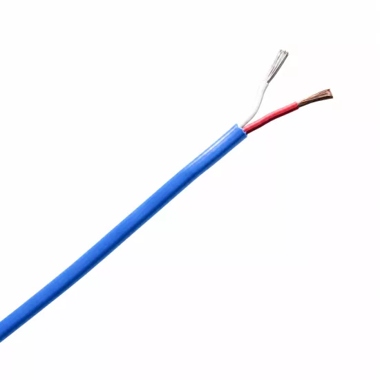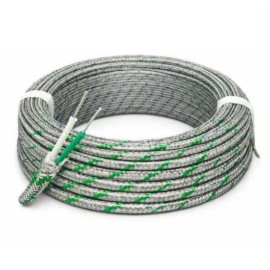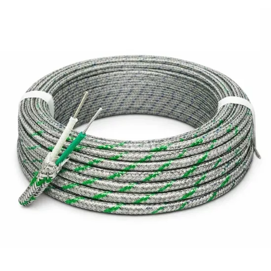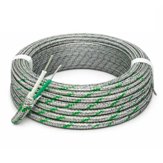
K-Type Metal-Braid Shielded Thermocouple Cable 2x0.22 mm² – Silicone / Teflon is a shielded thermocouple connection cable used to transmit the low-level temperature measurement signal from a K-Type thermocouple sensor to a controller, indicator, data logger, PLC, or automation system.
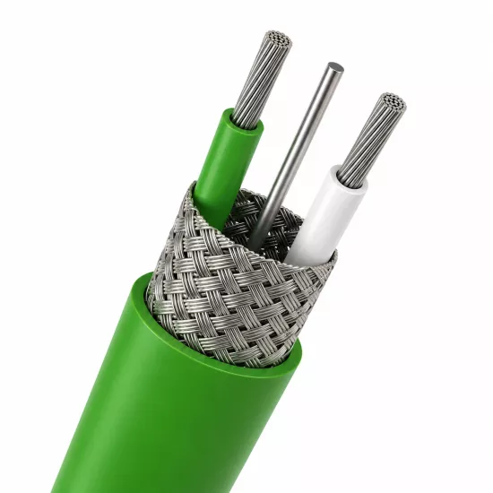
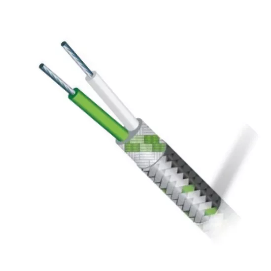
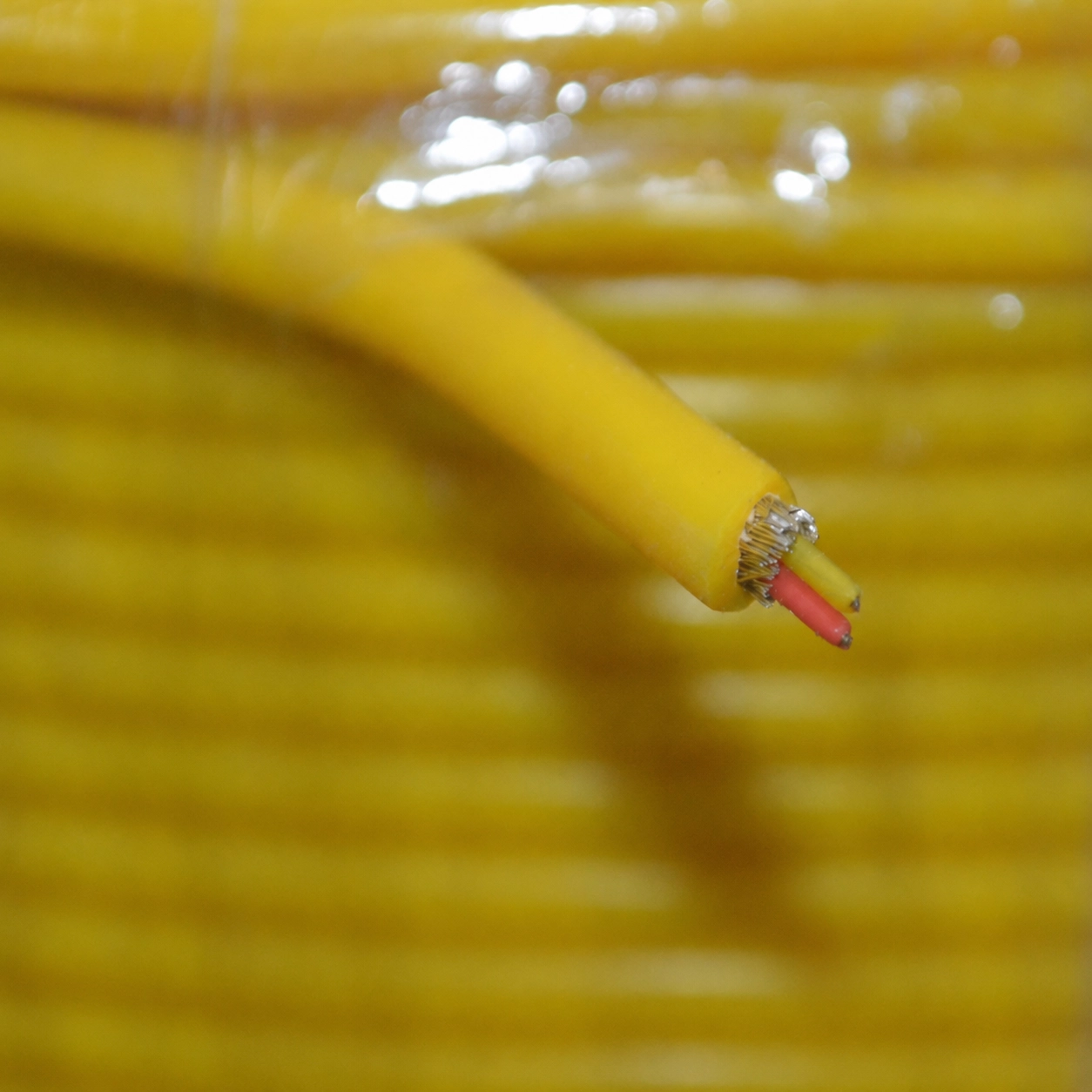
The cable consists of two stranded measurement cores, a metal braided shield surrounding the cores, Teflon core insulation and a yellow silicone outer sheath. Each measurement core consists of 7 wires with a diameter of 0.20 mm and corresponds to a nominal conductor cross-section of approximately 0.22 mm².
The metal braided shield helps reduce the effect of motors, inverters, contactors, relays, power cables, and similar electrical noise sources on the thermocouple measurement signal. This model has no separate drain wire. When a shield connection is required, the metal braid must be gathered using an appropriate method and terminated at a shield, chassis, or grounding terminal.
The product is not a standard power cable. It should be used for signal transmission in K-Type thermocouple measurement circuits. Yellow positive (+) and red negative (-) core polarity must be maintained during connection.
The outermost layer of the cable has a yellow silicone sheath. Silicone outer sheath gives flexibility to the cable and helps protect the internal structure in industrial working environments.
The positive and negative measuring wires are separated by insulation Teflon. Teflon insulation is a technical insulation structure used for electrical insulation and thermal resistance in temperature measurement cables.
Teflon has a metal braided shield around the insulated measurement cores. The metal braided shield forms a conductive shield layer around the measurement line, helping to reduce the coupling of surrounding electrical noise to the measurement cores.
The main function of the metal braid is electrical shielding. Although the braid structure provides some physical support to the cable, it should not be considered heavy-duty steel braid or mechanical protection shield.
Although this product has a metal braided shield, it does not have a separate drain wire. Metal braided shield and drain wire are not the same component.
Metal braided shieldis the conductive layer surrounding the positive and negative measurement cores. It helps to reduce the effect of external electrical interference on the measurement line.
Drain wire is a separate conductor that is in electrical contact with the metal braid in some shielded cables and facilitates connecting the shield to a terminal. Because this model has no drain wire, the shield connection must be prepared using the metal braid itself.
| Cable Component | Function | Connection |
|---|---|---|
| Yellow measurement core | Carries the positive side of the K-Type thermocouple signal. | Connects to the device's K-Type positive (+) terminal. |
| Red measurement core | Carries the negative side of the K-Type thermocouple signal. | Connects to the device's K-Type negative (-) terminal. |
| Metal braided shield | It helps reduce the effect of electrical noise on the measurement signal. | When necessary, the braid is collected and connected to the appropriate shield, chassis or grounding terminal. |
| Silicone outer sheath | It surrounds the internal cable structure and provides flexibility to the cable. | It is not an electrical connection component. |
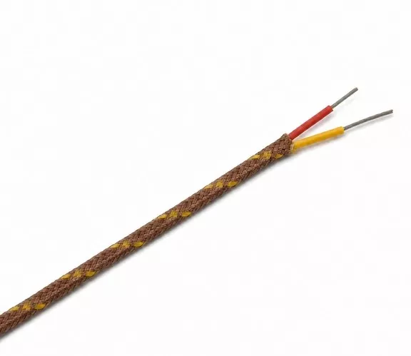
In this K-Type thermocouple cable ANSI color coding to identify the cores and their polarity. In a K-Type thermocouple circuit using the ANSI color scheme, the yellow core indicates the positive (+)and the red core indicates the negative (-) connection. The product's outer sheath is also yellow.
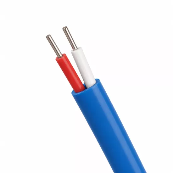
In the ANSI system, red color indicates the negative core of the thermocouple circuit. This point is especially important for users working with IEC color-coded cables because green positive and white negative cores are used in IEC K-Type cables.
Thermocouple cables may have different color coding systems such as ANSI, IEC and JIS. The same K-Type cable can be produced with different core and outer sheath colors depending on the standard used. For this reason, when making connections, you should not only look at color. The product's thermocouple type, polarity information and device terminal diagram should be checked together.
The manufacturer's product image gives the cable a temperature rating of 150°C and this value should be evaluated together with the cable's silicone outer sheath, Teflon core insulation, and shield construction.
The specified temperature value is not the total measurement range of the K-Type thermocouple sensor. It refers to the temperature of the environment where the cable is located. In the application, continuous operating time, mechanical movement, connection points, chemical contact and mounting type must also be taken into account.
Thermocouple sensors produce a low-level voltage signal. This signal can be affected by electrical noise from motors, inverters, contactors, relays, heating-element controllers, power cables, and similar sources.
The metal braided shield creates a conductive layer around the measurement cores, helping to reduce external electrical influences from reaching the signal line. For this reason, the product can be preferred in machine, panel and automation applications where electrical interference exists.
The metal braided shield does not completely eliminate electrical interference. Shielding performance depends on the cable route, shield termination, grounding arrangement, device-input configuration, and surrounding noise level.
In a K-Type thermocouple circuit, the yellow core must be connected to the device's positive (+) terminal and the red core to its negative (-) terminal. Reversed polarity may cause the indicated value to decrease as the temperature rises or the measurement value to change in the wrong direction.
The metal braided shield should not be connected to the positive or negative thermocouple terminal. If shield connection is required, the braid should be carefully assembled and terminated at the appropriate shield, chassis or ground terminal.
Because this model has no separate drain wire, a suitable connection end may need to be prepared from the braid so that it can be connected to a terminal. During connection, the braid wires must not contact the positive or negative measurement cores.
It is preferred for the shield to be terminated from a single point on the controller or board side in most measurement applications. However, the exact connection method must be determined according to the device manufacturer's terminal diagram and the EMC/grounding project of the facility.
Connecting the shield to different ground points at both ends may create a ground loop in some systems. Shield connection should not be made randomly without evaluating the application project.
The cable should not be run parallel to power cables for long distances in the same channel. Separating measurement and power cables as much as possible supports the protection provided by the metal braided shield.
The cable carries two thermocouple measurement cores. If a special thermocouple connector designed for the third pin shield connection will be used, the metal braided shield can be collected appropriately and connected to the third port.
Because this product has no ready-made drain wire, connecting a three-pin connector requires additional termination work compared with a model that has a drain wire. The third pin of every three-pin connector may not be designed for shielding or grounding. The connector's technical wiring diagram must be checked.
No. The main function of the metal braid in this product is electrical shielding. Although it may provide some physical support to the cable, it should not be used as heavy-duty mechanical armor against crushing, cutting, pulling or intense friction.
In areas with a risk of mechanical impact or abrasion, the cable must also be routed through flexible conduit, protective tubing, or a suitable cable duct.
When choosing a cable, thermocouple type, color code, conductor structure, core cross-section, insulation material, shield requirement, ambient temperature, cable route and the device to be connected should be evaluated together.
An unshielded cable may be sufficient for electrically quiet, short measurement circuits. A metal-braid shielded cable may be preferred in applications containing motors, inverters, contactors, and power cables.
Model with drain wire in applications where ready-made shield connection conductor is needed; In applications where a compact and drainage-free structure is required, this KAFPG model can be evaluated.
The product has the color code ANSI. In the K-Type ANSI arrangement, the yellow wire indicates the positive (+) connection and the red wire indicates the negative (-) connection. The outer sheath is also yellow.
No. In the ANSI thermocouple color system, the red core indicates the negative (-) connection. In this product, the yellow core is positive (+) and the red core is negative (-).
No. The metal braided shield is the shield layer surrounding the measurement cores. The drain wire is a separate conductor that facilitates the connection of the shield to the terminal. This model has a metal braided shield but no separate drain wire.
Yes. The metal braid can be collected appropriately and connected to the shield, chassis or grounding terminal. Care should be taken to ensure that the braid does not come into contact with the measurement cores and that the connection is made in accordance with the device diagram.
It indicates that the cable has two measurement cores, each with a nominal conductor cross-sectional area of approximately 0.22 mm².
It means that each measurement core consists of 7 thin wires, each 0.20 mm in diameter. This stranded construction makes the cable easier to shape.
The code is the manufacturer's code that identifies the two-core, stranded and shielded cable construction of the product. Material meaning should not be attributed to the letters KAFPG without the official code of the manufacturer.
No. The metal braided shield helps reduce the effect of electrical noise on the measurement circuit. The result depends on the cable route, shield connection, grounding arrangement, and level of interference in the environment.
The manufacturer's image specifies a cable temperature of 150°C. This value refers to the manufacturer's information about the cable's operating environment, not the thermocouple sensor's measurement range.
No. The product is used to transmit K-Type thermocouple measurement signals. It must not be used to power a motor, heating element, heater, or any other power load.
For the exact conductor alloys, outer diameter, electrical values and continuous operating conditions of the product, the 2x7x0,22KAFPG manufacturer's technical data sheet should be used as the basis. Technical values not verified by the manufacturer should not be considered the definitive usage limit of the product.




 EN
EN Türkçe